In the following, we would like to provide you with help for the correct design of a roller shutter drive.
Several components have to be taken into account:
What maximum output torque and reduction ratio must or should be used?
What crank projection is required for convenient operation in accordance with the standard?
Which spherical plain bearing is suitable for the load?
In order to simplify the calculation of the required output torque and make it more reliable, constants for the calculation were determined through extensive test series. The gearbox is selected in several steps:
Width (of the curtain in m) x height (of the curtain in m) x weight per square meter (of the profile used in kg according to the manufacturer’s specifications) = curtain weight in kg
Selection of the appropriate constant determined by the hanging height, the profile used and the shaft used
| Profile | Mini profile (8 mm) | Maxi profile (14 mm) | ||
|---|---|---|---|---|
| Hanging height | Shaft | 40 mm shaft 8-edge shaft | 60-shaft 8-edge-shaft | |
| up to 140 cm | 0,35 | 0,60 | 0,60 | |
| up to 240 cm | 0,42 | 0,60 | 0,65 | |
The “constant” includes the conversion from kg to Newtons, the effective lever length and a safety margin for friction.
Please note that various mechanical factors play a role in the calculation of the output torque, which cannot be taken into account in this “constant”.
These are for example:
The results are therefore approximate values for which we cannot accept any liability. The exact values can only be determined during a measurement by an experienced technician.
Armor weight x constant = required output torque of the gearbox
A roller shutter with a width of 1.25 m and a height of 2.20 m is used for a door element. A mini profile on a 60 mm shaft is used as the curtain. The specific curtain weight is 3.4 kg per m². Class 1 operation is required.
1.25 m x 2.20 m x 3.4 kg = 9.35 kg
9.35 kg x 0.6 (constant) = 5.6 Nm
For normal operation, the force to be applied to the crank handle should not exceed 30 N (corresponds to approx. 3 kg). This force corresponds to operating class 1 in accordance with DIN EN 13659. For easy and comfortable operation, the force to be applied to the crank handle should not exceed 15 N (corresponds to approx. 1.5 kg). This amount of force corresponds to operating class 2 in accordance with DIN EN 13659. You can find the required crank projection from the operating force diagram, which you will find with the selected gearbox, in order to achieve operation in accordance with one of the aforementioned classes.
Example: Selection of gearbox 444F… with 8.5 Nm output torque and a reduction ratio of 2:1.
As you can see from the blue lines, operating class 1 can be achieved with a crank projection of 120 mm!
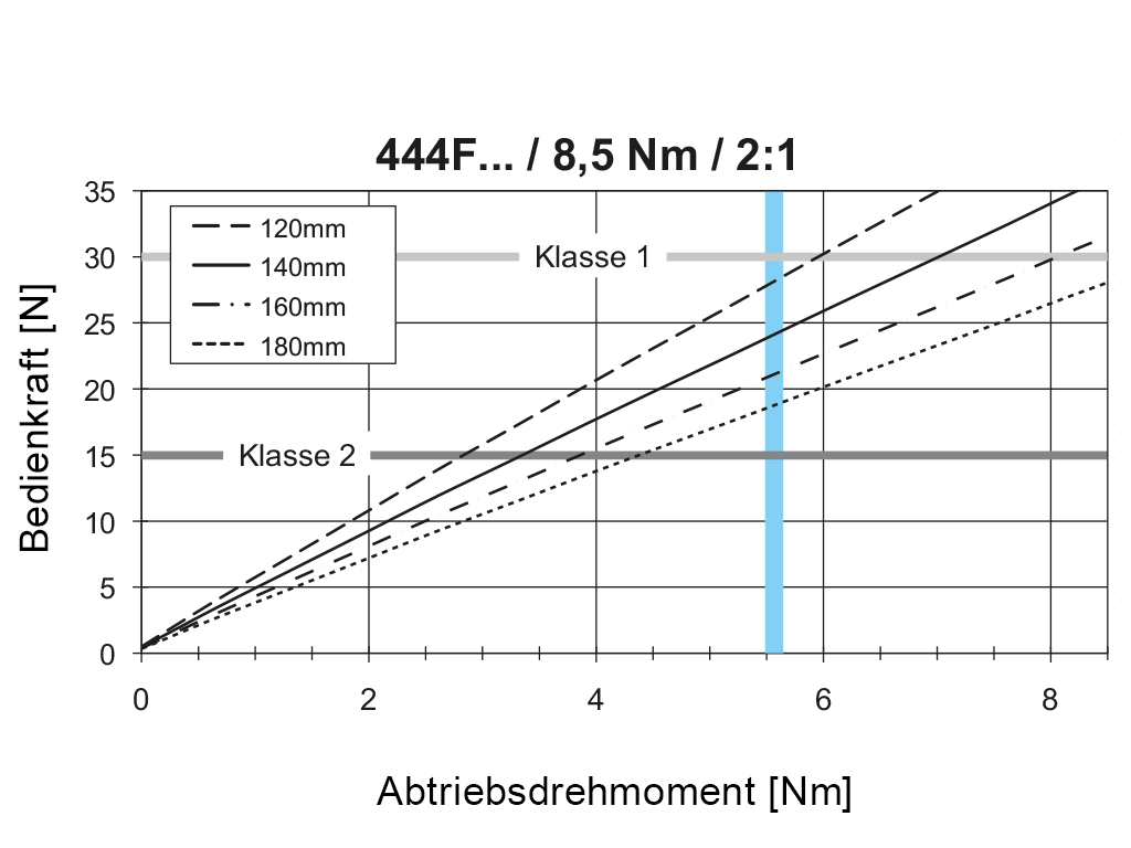
To achieve Class 2 operation, a different gearbox with a higher output torque and/or a different reduction ratio must be selected.
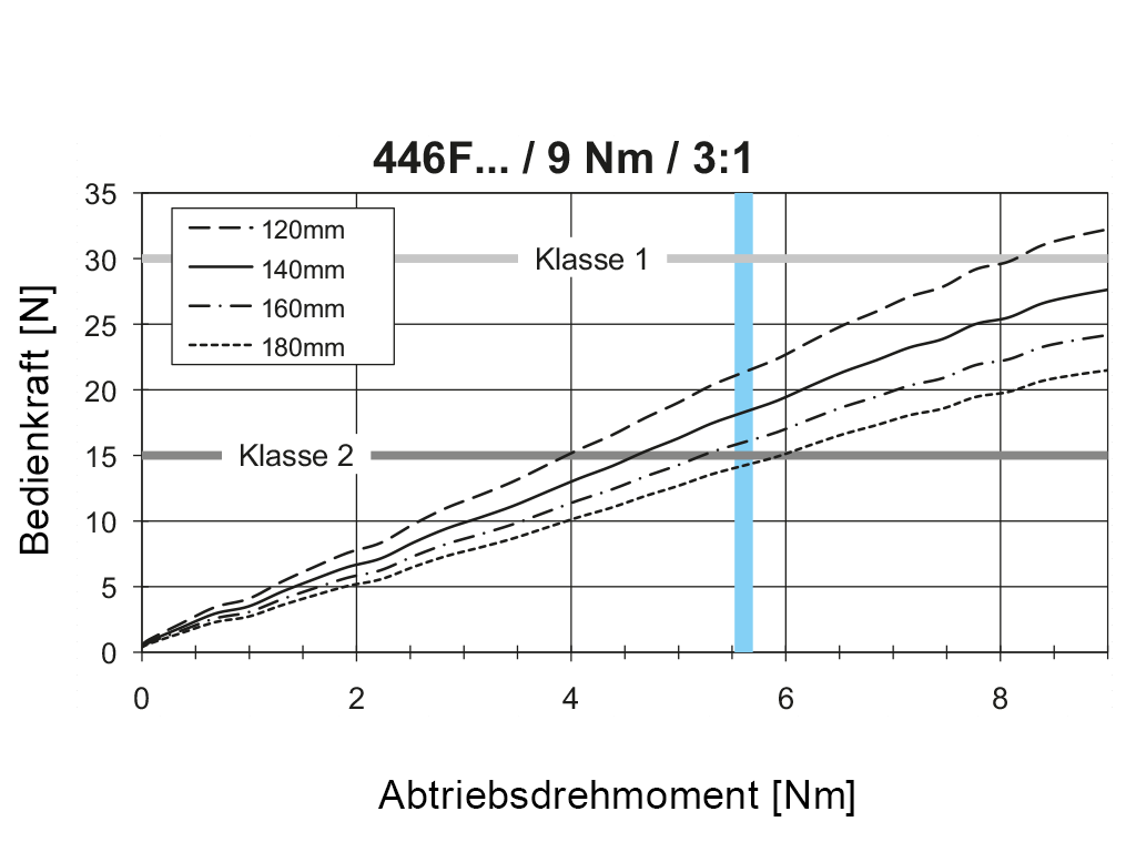
Alternative: Gearbox 446F… with 9 Nm output torque and a reduction ratio of 3:1
Thanks to the gear reduction (3:1), operating class 2 can be achieved here with an outreach of 180 mm.
For dimensioning the spherical plain bearing, it is important to know the resulting torque at the universal joint. For this purpose, after selecting the gearbox, the output torque calculated in step 1 is calculated with the values (reduction ratio and efficiency) of the gearbox.
(output torque : (reduction ratio)) : Efficiency = spherical plain bearing torque
The selected gearbox 446F… has a reduction ratio of 3:1 and an efficiency of 0.86.
(5.6 Nm : (3:1)) : 0.86 = 2.17 Nm
Up to 3 Nm spherical plain bearing torque, a spherical plain bearing 816F… made of steel can be used. Between 3 and 5 Nm, a spherical plain bearing 818F… made of aluminum must be used.
You are currently viewing a placeholder content from Elfsight. To access the actual content, click the button below. Please note that doing so will share data with third-party providers.
More Information